|
MetroVisionLab Toolbox for Camera Calibration and Simulation |
|
METROVISIONLAB package for camera calibration has been developed, designed and implemented by:
The METROVISIONLAB package runs on MATLAB 7.0 or higher. MATLAB® is a registered trademark of The MathWorks, Inc.
|
||||||||||||||||||||||||
|
|
||||||||||||||||||||||||
|
|
METROVISIONLAB for Camera Calibration and Simulation |
|
||||||||||||||||||||||
|
|
||||||||||||||||||||||||
|
Download package and source code |
||||||||||||||||||||||||
|
Case Studies:
|
||||||||||||||||||||||||
|
|
||||||||||||||||||||||||
|
DISCLAIMER:
Please use the following citation format:
|
||||||||||||||||||||||||
|
>> GENERAL DESCRIPTION OF METROVISIONLAB
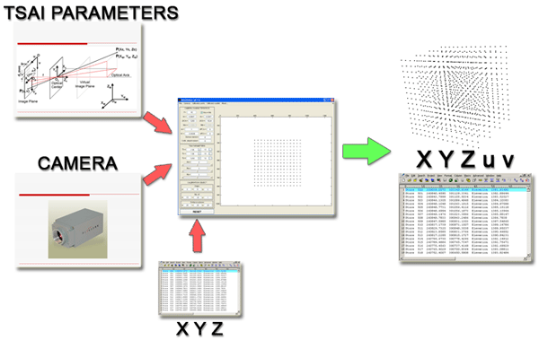
METROVISIONLAB is a toolbox developed for testing, from real or synthetic data, the behaviour of the main camera calibration techniques for use in machine or computer vision and dimensional metrology.
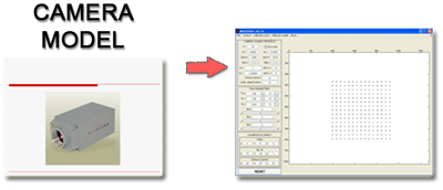
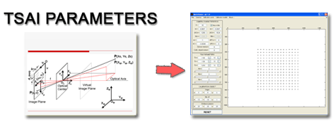
The main tasks that you can perform with METROVISIONLAB are shown in Fig. 1.
|
||||||||||||||||||||||||
|
|
|
|||||||||||||||||||||||
|
|
|
|||||||||||||||||||||||
|
|
||||||||||||||||||||||||
|
|
||||||||||||||||||||||||
|
||||||||||||||||||||||||
|
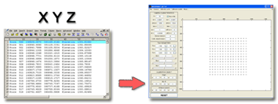
2.- Automatic generation of pairs of global and screen point coordinates of the calibration object. Analysis of best calibration positions. 3.- Variation of calibration parameters and its influence over camera image capture. 4.- Analysis of error mechanisms and parameter influence over camera calibration models. Monte Carlo analysis. 5.- Camera calibration from real and simulated data sets. 6.- Simulation of Gaussian noise in screen coordinates and in calibration gauge object. 7.- Accuracy analysis of calibration models for its use in dimensional metrology. 8.- Experimental points data sets verification and validation. 9.- Training exercises and computer vision teaching tasks for engineering students.
|
||||||||||||||||||||||||
|
>> USER GUIDE
>> Starting METROVISIONLAB
To start METROVISIONLAB for Camera Calibration type in MATLAB command window:
Metrovisionlab
>> Main Interface
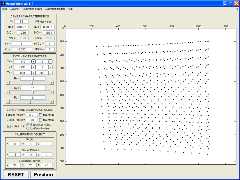
>> Configuration tools
>> View window
>> Menu structure and commands
>> Files menu
Establishes default values for camera characteristics, Tsai parameters and calibration object. This command is also executed when you press RESET button at the bottom of the main windows.
Opens a MetroVision Lab file (*.gen) and loads all configuration parameters to the interface.
Saves all configuration parameters of the current test in a MetroVision Lab file (*.gen) to be recovered executing the Open test command.
Loads a Tsai calibration file (*.cal). This file contains Tsai parameters that are loaded in the interface. Points in the view window are updated according to the loaded Tsai parameters.
Saves current Tsai parameters of the interface to a Tsai calibration file (*.cal).
Saves X, Y, Z global coordinates and corresponding u, v screen coordinates for the points obtained with current configuration parameters and showed in the view window. This command generates a Calibration points (*.pto) file.
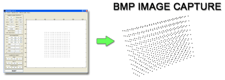
Captures and saves a image (*.bmp) of the view window to a file.
>> Cameras menu
>> Calibration points menu
-Load points (X, Y, Z)- When checked, this options loads the calibration points from a Calibration points (*.pto) ascii file and updates the view window according to configuration parameters. Each row of that file represents the global coordinates of the point in the format: X Y Z X Y Z … X Y Z If you use this generation mode in a file with more than three columns (e.g. X Y Z u v), only the first three columns are loaded according to the specified format.
When checked, this options loads the calibration points from a Calibration points (*.pto) ascii file and updates the view window according to configuration parameters. Each row of that file represents the global and screen coordinates of the point in the format: X Y Z u v X Y Z u v … X Y Z u v This mode allows to load global and screen coordinates pairs of calibration points to test the calibration algorithms.
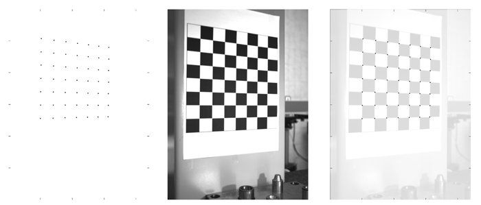
-Chessboard (only coplanar)- When checked, a chessboard is used as gauge calibration object, providing the calibration points according with the values specifiend in the CALIBRATION OBJECT frame. When this generation technique is used, some options in this frame are disabled, since it is only allow to use the chessboard as gauge object with coplanar calibration points.
It is the default generation mode for the calibration points. When checked, the calibration object points showed in the view window are controlled by the parameters specified in the CALIBRATION OBJECT frame.
>> Calibration models menu
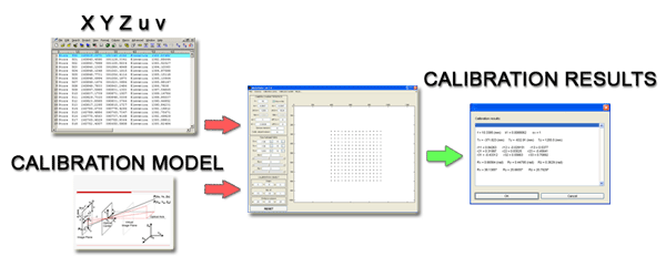
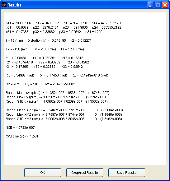
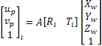
The results of intrinsic and extrinsic parameters and transformation matrix terms obtained are shown after each calibration (Fig 4.). Also, caracteristic parameters depending on the calibration method chosen are shown. You can save the calibration results to a file for later analysis.
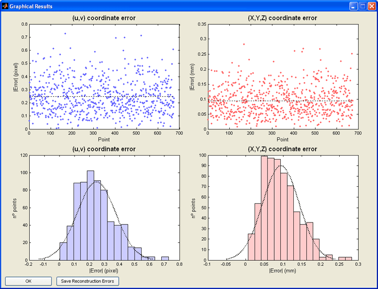
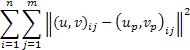
In the Results window, it is possible to represent graphical results of the calibration (Fig. 5). This option shows graphs for the reconstruction errors of the calibration points, both in image coordinates and world coordinates. This tool is suitable to obtain characteristic parameters of the calibration carried out, and to have an overall idea of the later measurement error with the current calibration. The button “Save Reconstruction Errors” saves to file the reconstruction error for the calibration points used in each coordinate.
Figure 5. Reconstruction errors for the calibration points in image and world coordinates.
Those commands allow to study the influence of error sources over calibration model chosen and the behaviour of the different calibration models.
>> Help menu
Shows general information about the Toolbox.
|
||||||||||||||||||||||||
|
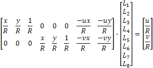
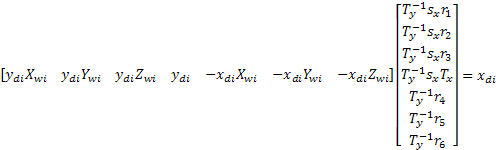
>> DLT Model (Direct Linear Transformation)
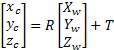
It is based on the colineality
between a point expressed in world frame |
||||||||||||||||||||||||
|
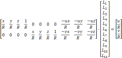
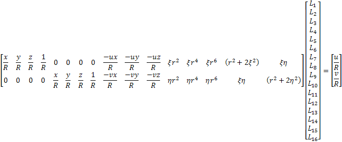
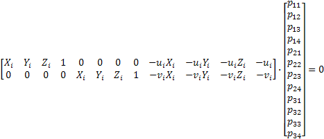
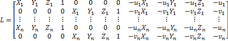
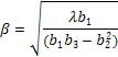
DLT calibration consist of calculate the eleven parameters, and since each point provides two equations, a minimum of six points to calibrate is necessary.
To improve the results obtained by this method is necessary to include in the above equations the correction of errors caused by optical lenses distortion and deviation of the optical center.
Where
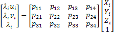
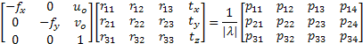
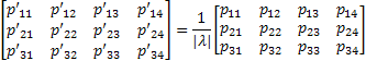
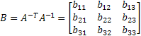
Once obtained the coefficients of DLT method, it is possible to calculate intrinsic and extrinsic parameters of the calibrated camera. With the above coefficients, whether the optical defects have been corrected or not, you can create the following projection matrix:
Terms
Therefore, one can calculate the scale factor as:
Once normalized
Where
Where
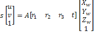
The decomposition of projection
matrix
It is only necessary to replace
It is identical to the DLT 3D method
except for the fact that
>> DLT REFERENCES
· Abdel-Aziz, Y.I., Karara, H.M. (1971). Direct linear transformation from comparator coordinates into object space coordinates in close-range photogrammetry. Proceedings of the Symposium on Close-Range Photogrammetry (pp. 1-18). Falls Church, VA: American Society of Photogrammetry. · Shapiro, R. (1978). Direct linear transformation method for three-dimensional cinematography. Res. Quart.49, 197-205. · Liu, H.T. (2001). Video-Based Stereoscopic Imaging and Measurement System (SIMS) for Undersea Applications. MTI/IEEE Proc. Oceans 2001 Conf., Honolulu, Hawaii. · Hatze, H. (1988). High-precision three-dimensional photogrammetric calibration and object space reconstruction using a modified DLT-approach. J. Biomech 21, 533-538.
Tsai method for calibration is based
on the pin-hole camera model. This model transforms points in world reference
frame The transformation between world coordinates
1.-Firstly, world coordinates
2.-Next step consist of converting
the coordinates of the points from camera reference frame
3.-In the third step undistorted
sensor coordinates
4.-In the last step the coordinates
of the points are transformed from the sensor reference frame with distortion
From the point of view of the Tsai
calibration method, two different steps can be distinguished. In the first
step, orientation From the image captured by the
camera, the screen coordinates of calibration points
Where
If none of the rows and columns in
On the other hand, if any of the
rows or columns of
Where
If
In the term
Once obtained With the calculated values of
With the approximation calculated
for
Once obtained all the calibration parameters, the following equation is optimized to obtain definitive values of the intrinsic and extrinsic parameters.
From the point of view of the Tsai
calibration method, two different steps can be distinguished. In the first
step, orientation From the image captured by the
camera, the screen coordinates of calibration points
Where
In the calculation of Ty,
it exists ambiguity in its sign, reason why it must be determined. For that,
any calibration point
If
At this point, the rotation matrix
Once obtained With the calculated values of
With the approximation calculated
for
Once obtained all the calibration parameters, the following equation is optimized to obtain definitive values of the intrinsic and extrinsic parameters.
>> TSAI REFERENCES
· Tsai, R.Y. (1986). An Efficient and Accurate Camera Calibration Technique for 3D Machine Vision. Proceedings of IEEE Conference on Computer Vision and Pattern Recognition, Miami Beach, FL, pp. 364-374. · Tsai, R.Y. (1987). A Versatile Camera Calibration Technique for High-Accuracy 3D Machine Vision Metrology Using Off-the-Shelf TV Cameras and Lenses. IEEE Journal of Robotics and Automation, Vol. RA-3, No. 4, pp. 323-344. · Willson, R.G., & Shafer, S.A. (1994). What is the Center of the Image? Journal of the Optical Society of America A,Vol. 11, No. 11, pp.2946-2955. · Tapper, M., McKerrow, J., Abrantes, J. (2002). Problems Encountered in the Implementation of Tsai's Algorithm for Camera Calibration. Proc. 2002 Australasian Conference on Robotics and Automation, Auckland. · Kim, D. (2006). Camera Calibration. 2006-SN-003-EN Unpublished. Intelligent Systems Research Center. SungKyunKwan University. Korea.
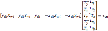
The calibration method proposed by Faugeras is very similar to DLT 3D model where no optical defects are corrected.
This calibration method is to find a
projection matrix that relates image coordinates
Where
To obtain the twelve terms of the projection matrix it is enough to solve the following equation. Since each calibration point provides two equations, at least six calibration points are needed.
One way to solve the above equation,
is to apply SVD decomposition to the matrix
The twelve terms of the projection
matrix
The first step is to calculate the
scale factor
Therefore:
Once normalized
Where
Where
The decomposition of projection
matrix
It is only necessary to replace
>>CORRECTION OF OPTICAL DISTORTION IN FAUGERAS METHOD
To eliminate optical distortion
during Faugeras calibration, correction polynomials are used, considering two
coefficients of radial distortion correction
Where:
First of all, an initial calibration
according to Faugeras method is carried out to achieve an approximation to
the projection matrix
The distorted sensor coordinates
Once known the image coordinates without distortion and the distorted sensor coordinates, the equations of distortion correction can be written in matrix form:
Where Once obtained the approximations to
Where
>> FAUGERAS REFERENCES
· Kim, D. (2006). Camera Calibration. 2006-SN-003-EN Unpublished. Intelligent Systems Research Center. SungKyunKwan University. Korea. · Faugeras, O. (1993). Three-Dimensional Computer Vision: A Geometric Viewpoint, The MIT Press.
Zhang model is a camera calibration method tha uses traditional calibration techniques (known calibration points) and self-calibration techniques (correspondence between the calibration points when they are in different positions). To perform a full calibration by the Zhang method at least three different images of the calibration gauge are required, either by moving the gauge or the camera itself. If some of the intrinsic parameters are given as data (orthogonality of the image or optical center coordinates) the number of images required can be reduced to two.
In a first step, an approximation of the estimated projection matrix with one of the classical calibration methods is obtained, usually DLT or Faugeras. Subsequently, applying self-calibration techniques, it is obtained the absolute conic matrix that allows us to calculate the intrinsic parameters matrix, and from this, the rotation and translation matrices for each of the images. Finally, radial distortion is modeled by means of two coefficients, and all the parameters obtained above are optimized, but taking into account the distortion.
>> ZHANG
First of all it is necessary to obtain an approximation of the projection matrix
Where
Once obtained the projection matrix
By minimizing
Where
Beeing
Using
Where
By solving the avobe system (SVD decomposition)
we obtain the vector
Starting from
Due to possible errors, both in the extraction of points as in the manufacture and gauge measurement, rotation matrix
It is only necessary to replace
Whre
The last step of the model is to correct the radial distortion caused by lenses in the image coordinates of the points. Being
First it will be needed to calculate an approximation of the distortion coefficients
Once obained the estimation of the coefficients, it is performed an optimization similar to that used to refine the parameter matrices of the camera, but this time the below equation is minimized:
>> ZHANG REFERENCES
· Zhang, Z. (2000). A flexible new technique for camera calibration. IEEE Transactions on Pattern Analysis and Machine Intelligence, 22(11):1330-1334. · Zhang, Z. (1999). Flexible Camera Calibration By Viewing a Plane From Unknown Orientations. International Conference on Computer Vision, Corfu, Greece, pages 666-673.
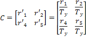
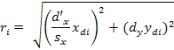
>> NCE Coefficient (Normalized Calibration Error)
NCE coefficient provides a value that gives an idea of the accuracy reached in a calibration test. This coefficient is independent of the conditions of the test (camera position and orientation, calibration gauge object position and orientation, camera field of view, camera resolution,...). Thus, not only several calibration test can be compared, but also it is possible to compare calibrations carried out with the different camera calibration methods without the influence of the peculiarities of each one.
Where:
being
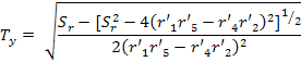
If
>> NCE REFERENCES · Juyang, W., Cohen, P., Herniou, M., (1992). Camera Calibration with Distortion Models and Accuracy Evaluation. IEEE Transactions on Pattern Analysis and Machine Intelligence, Vol. 14, No. 4, pp. 965-980.
MetroVisionLab for Camera Calibration and Simulation |
||||||||||||||||||||||||